Introduction
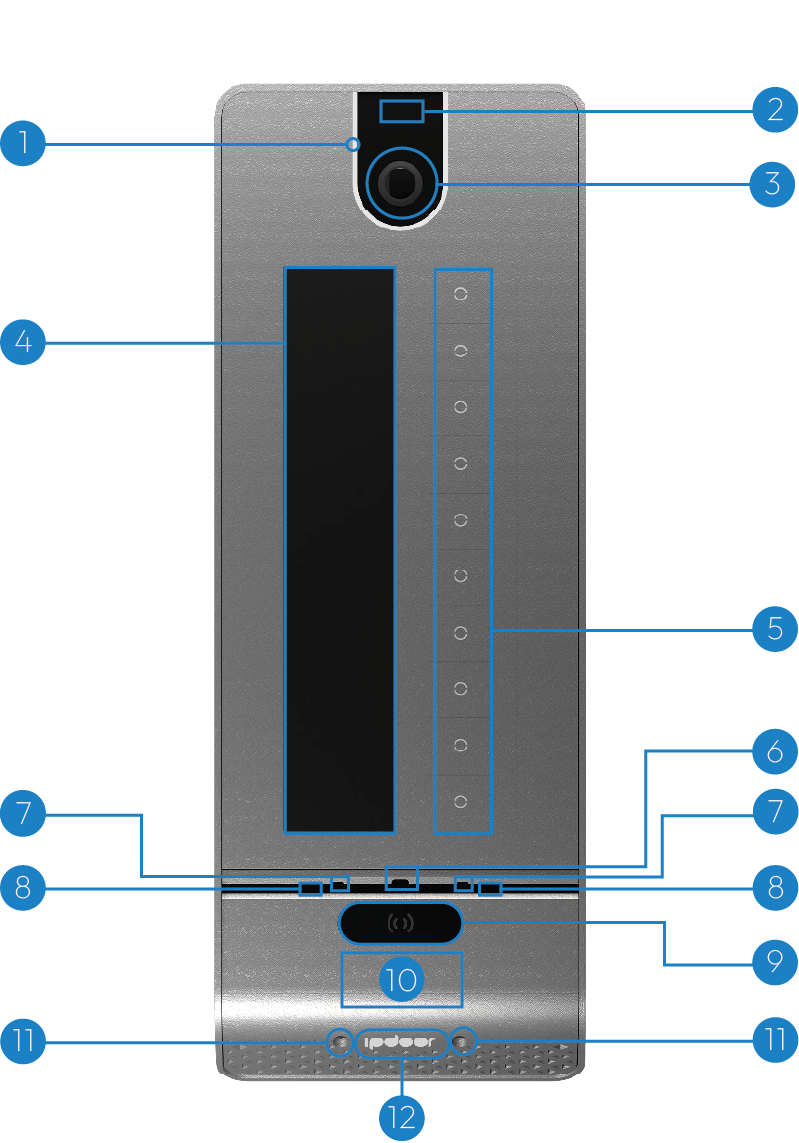
- 1.Front LED light
- 2.Proximity radar
- 3.Panoramic camera
- 4.Touch screen
- 5.Metal keys
- 6.Brightness sensor
- 7.Microphones
- 8.Infrared led
- 9.Facial recognition cameras
- 10.NFC reader
- 11.Lights of the lower
- 12.RGB color illuminated logo
Mechanical installation — Wall support
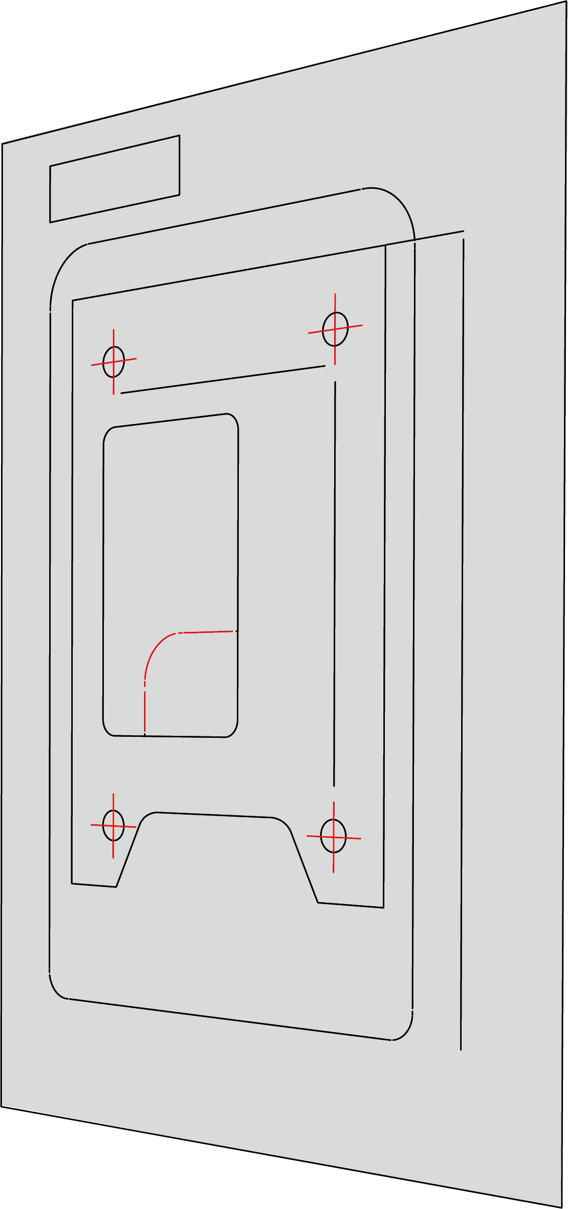
- Step 1 — PreparationPlace the DIMA on the wall,with the holes at the top at a height from the ground between 155 and 165 cm, making sure that the "TOP" side is facing up. Draw with a pencil the positions of the four holes highlighted in red in the figure.
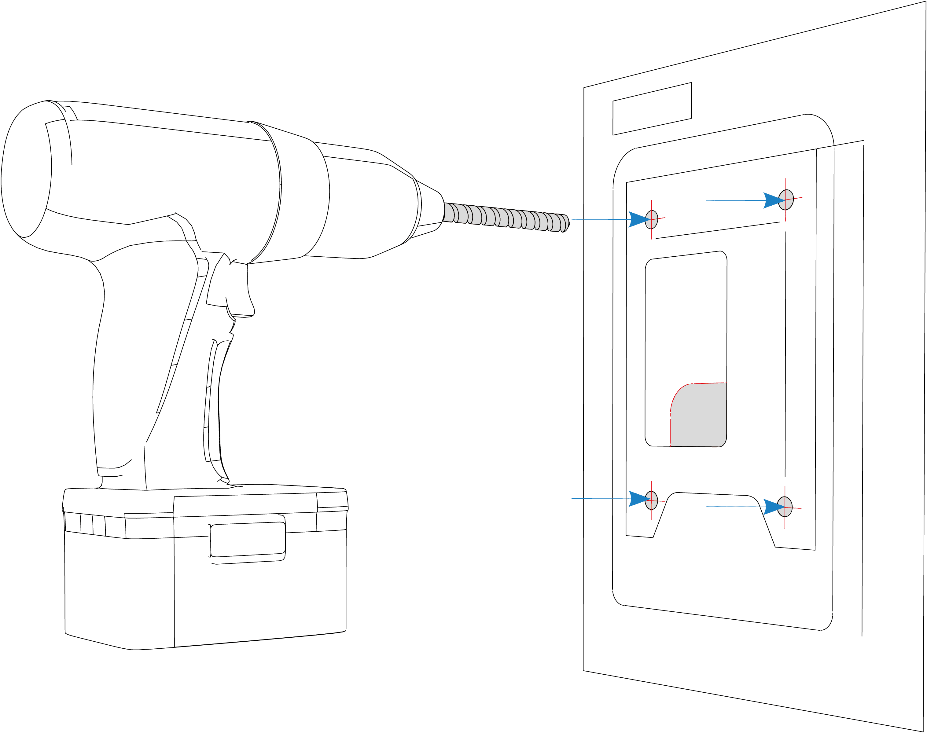
- Step 2 — CheckBefore proceeding, carefully check that there are no cables or pipes behind the wall, then drill holes in the wall at the previously drawn points.
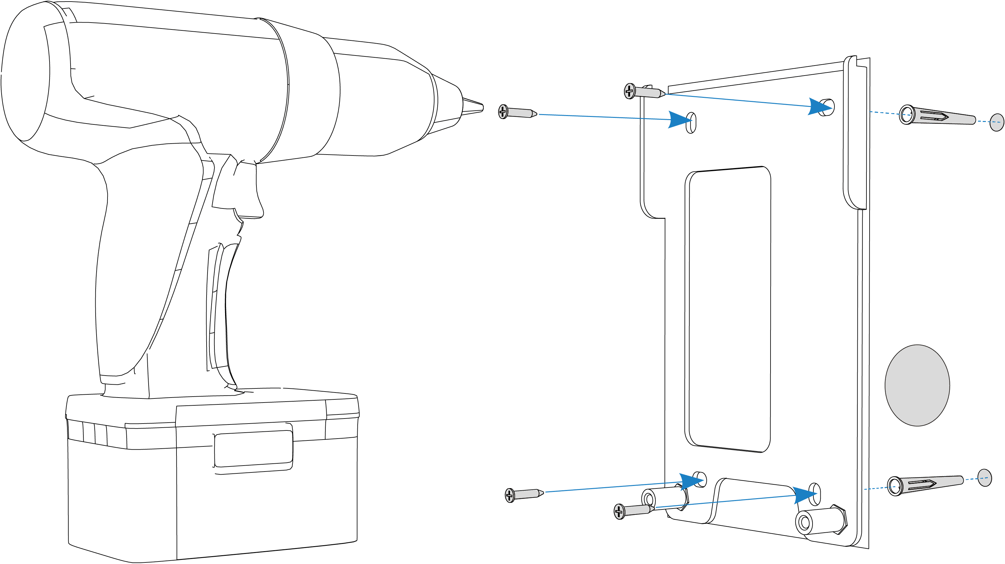
- Step 3 — DrillingInsert the dowels making sure they are perfectly flush with the wall. Then apply the fixing plate and secure it using the four screws provided, as shown in the figure.
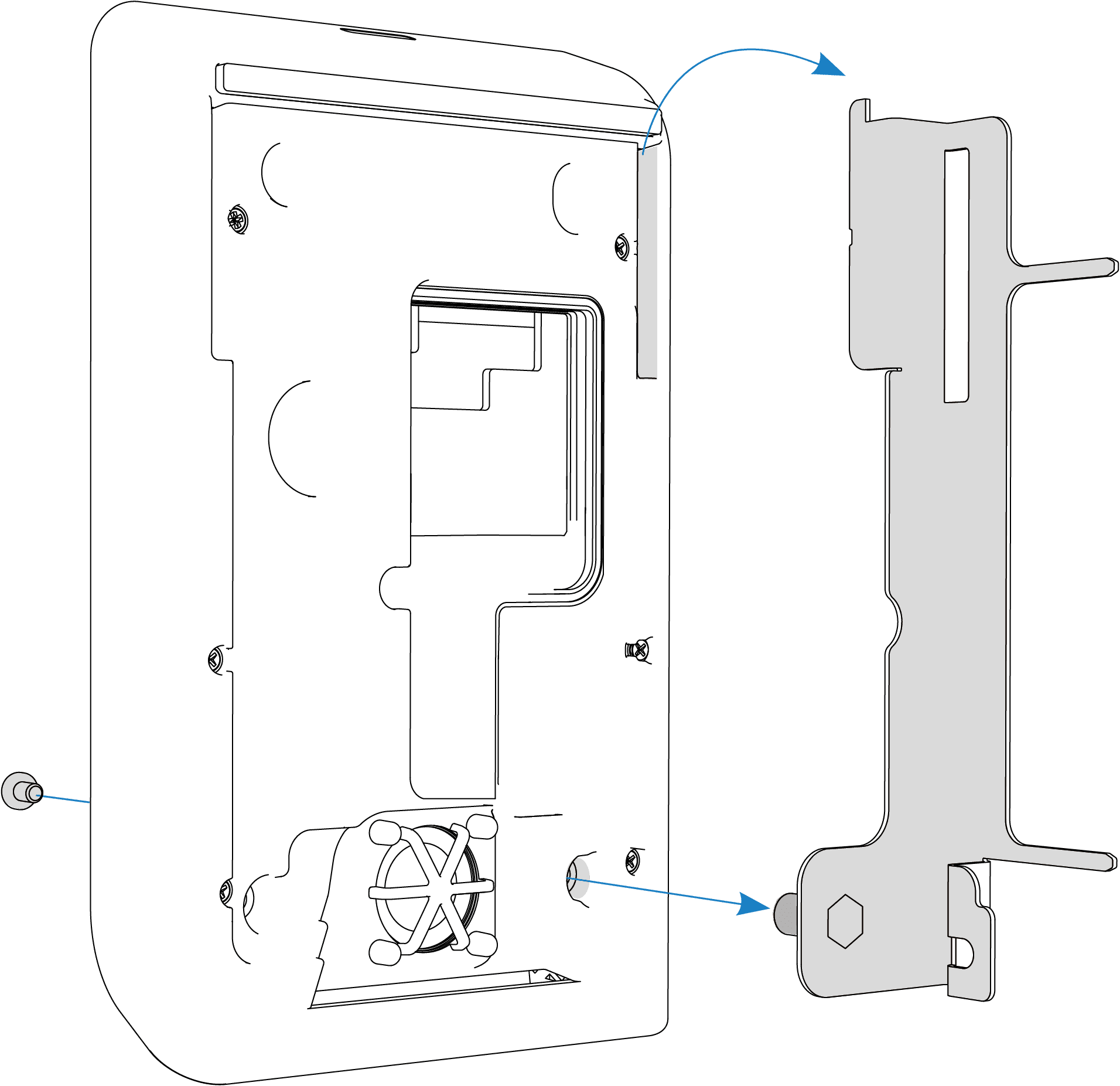
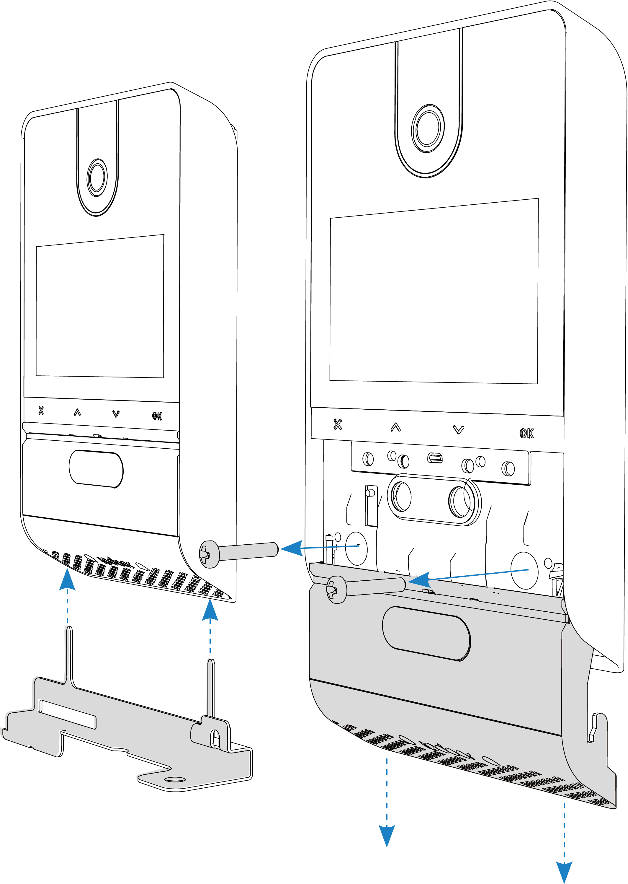
- Step 4 — Installation supportTo facilitate connections to the terminal block, a stand is available to support the plate during wiring operations. Attach the stand to the plate and tighten the front screw, as shown.
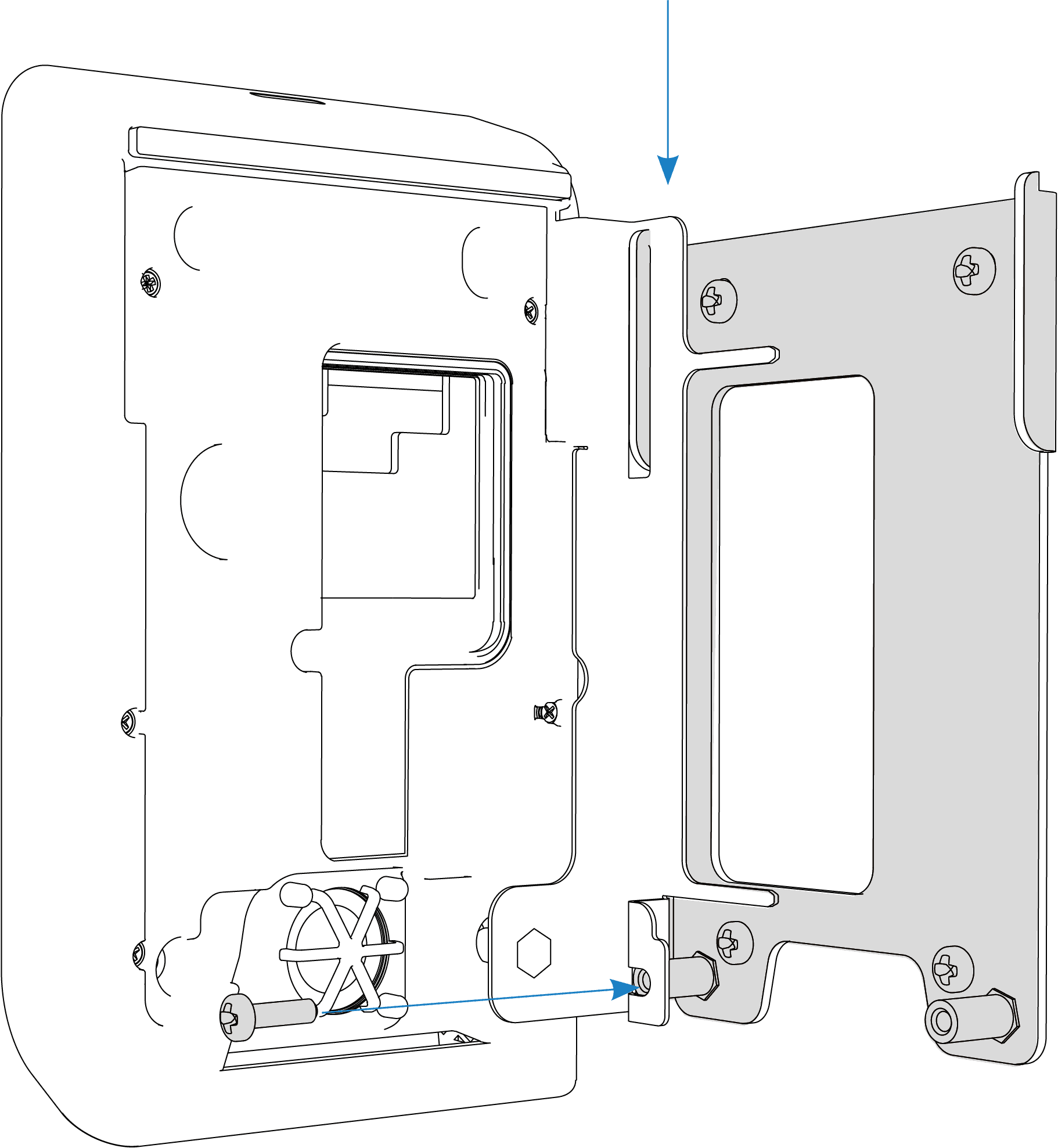
- Step 5 — Plate fixingThen proceed by hooking the stand to the plate and connect the cables to the terminal block. Once the connections are completed, unhook the stand from the plate and then from the device.
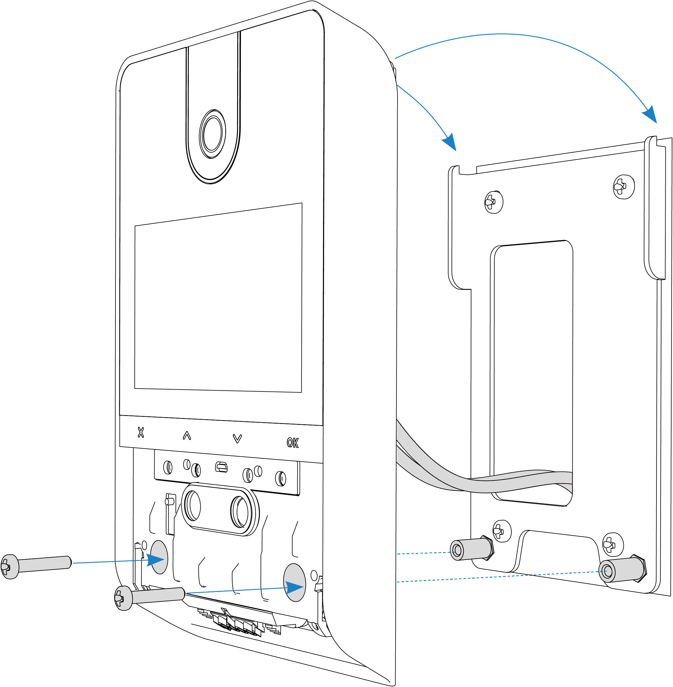
- Step 6 — Fixing deviceHook the plate onto the plate and screw in the two front screws as shown in the figure.
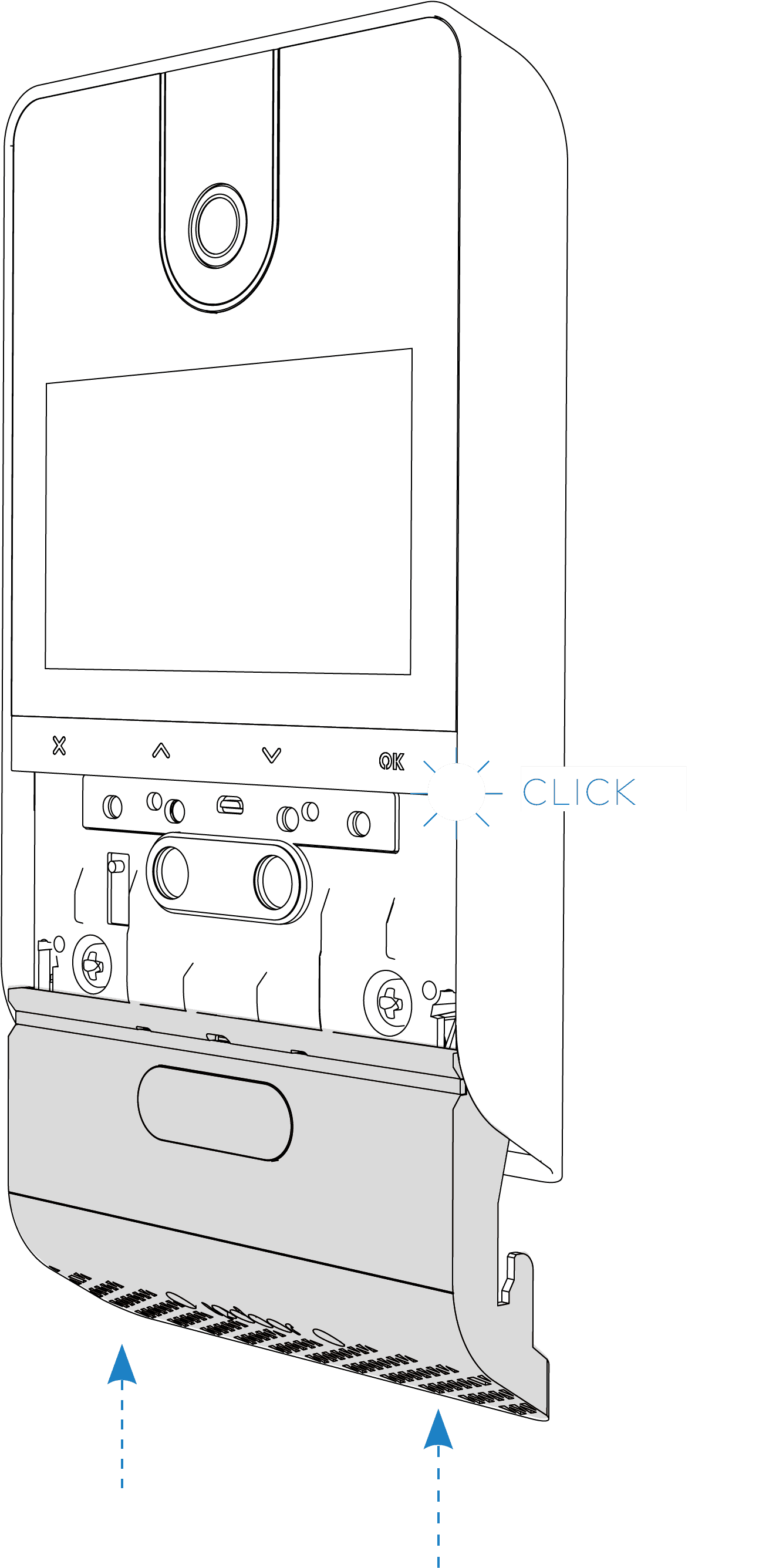
- Step 7 — ClosingTo complete the installation, insert the cover from bottom to top until you hear it click.
- Step 8 — DisassemblyTo uninstall the plate, insert the safety wrench into the slot on the bottom of the cover, push the cover down, and unscrew the front screws.
Electrical connections
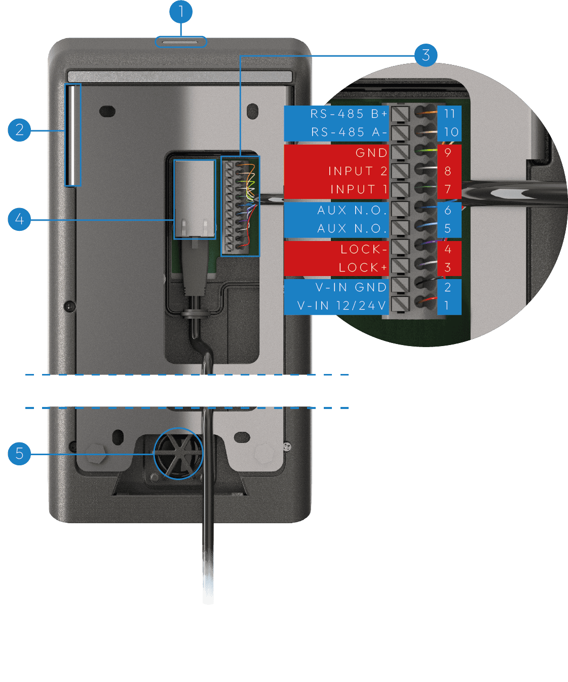
- Step 1 — PreparationWIRING ACCESS: After unscrewing the cover, remove the front screw at the bottom and rotate the holder so that the terminal area can be accessed. Locate the PoE input and other power terminals (as needed as described in the next steps).
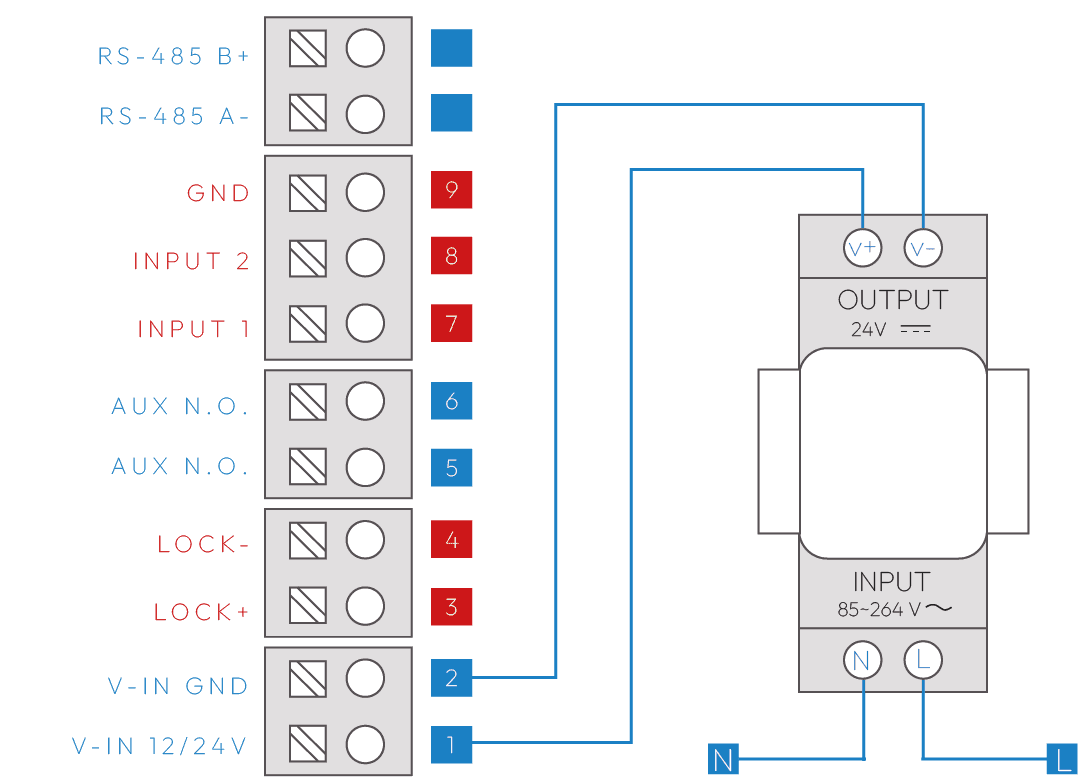
- Step 2 — Optional Power SupplyOPTIONAL POWER SUPPLY: If the Ethernet network is not PoE, a 24VDC/1A power supply must be used. Connect the power supply to the terminals indicated.
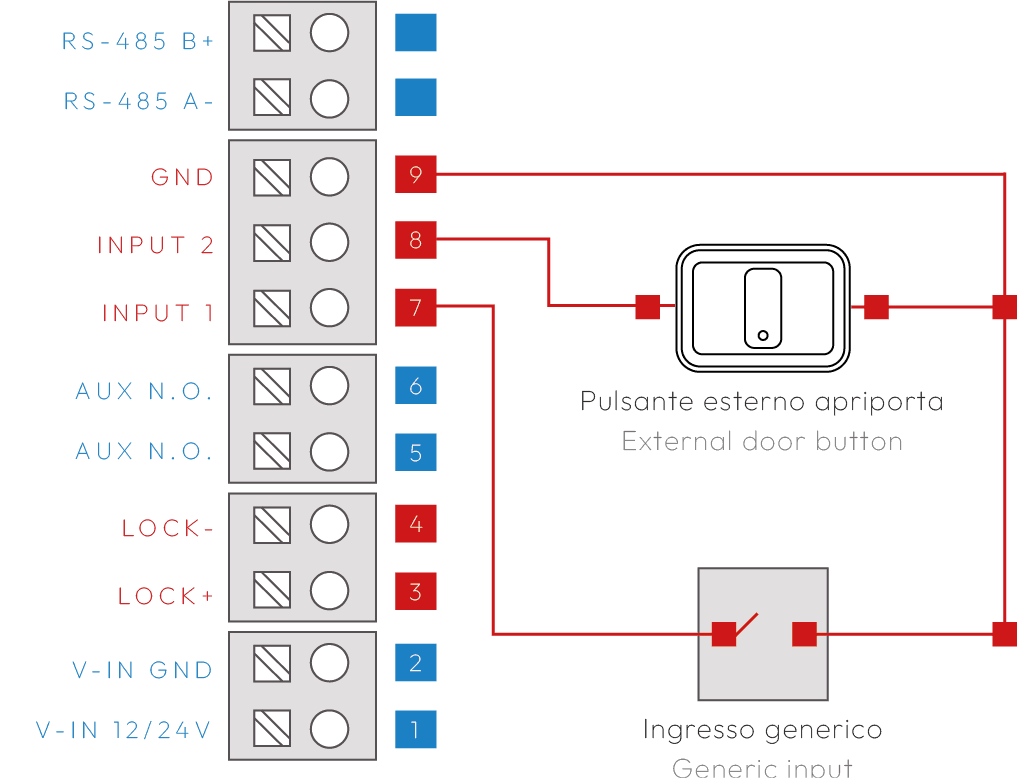
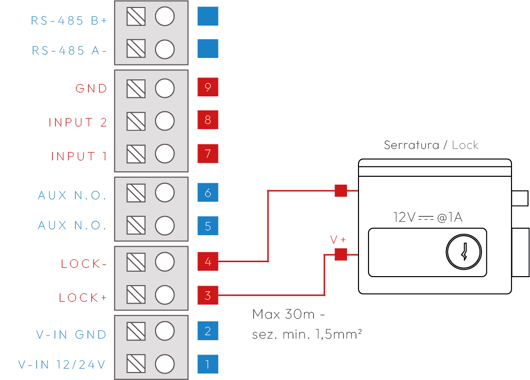
- Step 3 — Direct connection LockLOCK OUTPUT: An electric lock can be directly connected to the LOCK+ / LOCK- terminals (max 1A, cable ≤30m, 1.5mm²). An intermediate relay must be used for different loads, as shown in the application diagrams.
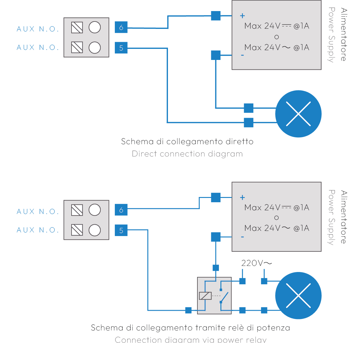
- Step 4 — Powered Lock ConnectionAUX OUTPUT: In this case the output is a dry contact switch that can drive an external load. If the load is in 220VAC, a power relay must be used.
- Step 5 — Connecting Button InputsINPUTS: Up to two inputs (e.g. external door opener buttons) can be connected. The inputs are programmable. Example of external door opener button on INPUT 1 / GND.